An Inexpensive External GPS Antenna (Part 1)
Final Assembly
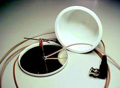
I’ve found that an empty, upturned 8-ounce cream cheese container makes a practical radome for the antenna. More importantly, it helps protect the internalworkings from mechanical damage.
I usually don’t paint the container but I do remove the silk-screened label by using an automotive rubbing compound. It takes some effort but it does come off. Just follow the manufacturer’s instructions. Be careful not to apply too much pressure to the lid when you rub the label off. It’s made of a different plastic than the container and stretches easily.
You should be able to snap the base plate into the lid of the container. It’s a tight fit so just work your way around the lid until the entire base plate is flush with the lid bottom You might have to cut a notch in the lip of the lid to allow the coax to exit the unit cleanly. Carefully align the coax with the lid notch and snap the cover onto the lid. It’s normal for the top of the transmission line assembly to slightly raise the “bump” on the container bottom.
Theory of Operation
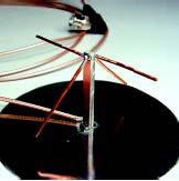
In a normal turnstile, we would have a double dipole configuration with both dipoles on the same plane but rotated 90° from each other. Additionally, the second dipole is fed 90° out of phase with an other ¼ wavelength of coaxial cable. This creates some difficult assembly problems since you would have to isolate the second dipole section from ground while maintaining the tight distance and spacing requirements. Due to the size constraints, this second dipole connection would require a very small diameter coax that might be difficult to work with and even harder to obtain. With this antenna, we cheat a bit and use a selfphased quadrature type feed.
To obtain circular polarization without a coaxial phasing line, the shorter dipole is cut so its impedance is 50 – j50 Ω. The longer dipole is fashioned into an inverted V shape and cut so its impedance is lowered to 50 + j50 Ω. With the combined asymmetrical dipoles and with them spaced slightly closer than ¼ wavelength to the ground plane, the antenna’s impedance is near 50 Ω with a much more omnidirectional pattern, an important consideration for reception of GPS satellites close to the horizon.
Operation
Connect the antenna to the GPS receiver and watch the signal-strength indicator.You should see an improvement over the supplied stock antenna. You can tweak the antenna by bending the wires up and down gently and watching the results on your GPS unit. Be careful of the solder joint—it’s rather fragile. Adjust for maximum displayed signal. Repositioning the


antenna may also improve reception. With this antenna, I routinely receive five to eight satellites on my Garmin II receiver. If you are using a GPS unit that sends dc voltage volts up the coax to power an external preamp or amplified antenna, don’t worry. Since the elements are not grounded or shorted, there is no dc path. Just be careful not to let either end of the active elements touch ground.
[Be advised that some GPS receivers with internal patch antennas have an antenna switching circuit. This circuit disables the internal antenna when an amplified external antenna is attached. The receiver senses current flow that is intended to power the amplifier of the external antenna.
If your receiver has this feature, you will want the switch to activate and disable the internal patch antenna. Placing
1 kΩ to 5 kΩ across the ground and center conductor of the coax should be sufficient. Check with the manufacturer of your GPS receiver.—Ed.]
If you are mobile, most GPS receivers will do a fair job of receiving signals through the windshield of a car. During the
summer, however (and especially out here in the Southwest), the GPS gets baked while sitting in the hot sun.
Obviously, one way to solve this problem is to locate the receiver somewhere cooler and place this external antenna on the dash. Once that’s done, you’ve protected your expensive receiver while sacrificing a $10 antenna.
This design was not intended for outside use, hence the lack of external mounting suggestions. Any prolonged exposure to the elements will degrade the antenna’s unprotected metal parts. My suggestion—if you plan on using this unit outside, at least spray the metal parts with clear lacquer and seal the exposed coax end with RTV. Otherwise, don’t waste a lot of time weatherproofing it. Because these antennas are so cheap and easy to build, if one does deteriorate throw it away and build another. Perhaps you might want to keep a couple of spares on hand, just in case.


